Organizing wells with grouping and filtering
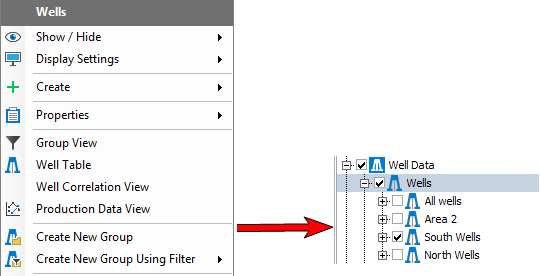
The Create New Group option click to enlarge
If you have a large number of wells in your solution, by default they will all be visible in the JewelExplorer and your views, and in lists in the various forms. This might be what you want, but it can also be somewhat burdensome to work with such huge lists of wells. By creating new groups, or by using grouping and filtering, you can group multiple wells together and visualize the wells on a group by group basis. You can do this with both wells and well designs.
At the most basic level, grouping provides a means for ordering and organizing the JewelExplorer with regards to these objects. Using groups can make an otherwise cluttered JewelExplorer more orderly and easier to work with.
Grouping objects, when combined with filtering (explained below), can help you with visualizing your wells in your 3D View. You can sort and view them by type or status (whether they are included in the model data or not) as well as many more filtering options that you can use to quickly and easily visualize the desired wells.
Creating a well group
With the JewelExplorer
To create a new group, right-click on the Wells folder in the JewelExplorer and select Create New Group from the context menu. Your newly created group will appear in the JewelExplorer. The example shows three user created groups; Area2, North Wells, and South Wells. Initially, the group will be called 'Group 1', but you can readily rename it.
Using the Group view
You can also create a group, and add wells to it, using the special Group view. Right-click on the Wells folder in the JewelExplorer and select Group View from the context menu. For more on the Groups view, including how you can filter the wells, see Using the Groups view and filtering wells.
By cross section
A well group can be created from any cross section in your solution. To create a well group via cross section, right-click the cross section of interest in the JewelExplorer and select the Create well group option from the context-menu. A well group named for the cross section is created under the Wells item in the JewelExplorer and is populated with all of the wells within the wellbore projection distance of the cross section. The wellbore projection distance parameter can be reviewed and changed in the Inspector to better control which wells are included as part of the cross section. To adjust this distance, first click the cross section in the 3D View or the JewelExplorer to make it the active item in the Inspector, then find and change the Wellbore projection distance option in the Geometry option group.
When you display wellbores or point set data on a cross section that consists of more than one pane in a Seismic View or a Cross Section View, JewelSuite projects the wellbores and point set data using a non-orthogonal method. An advantage of the non-orthogonal projection is that you will get a consistent cross-section in either view, i.e. objects are projected in the right order, which is less likely to be the case for orthogonal projection.
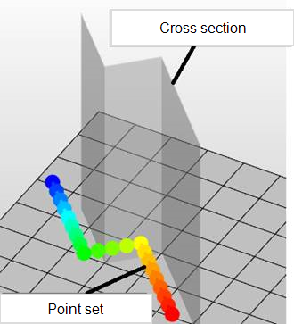
Point set with distance to cross section. When viewing this point set projected on the cross section in the Seismic View or Cross Section View, a non-orthogonal method is used. click to enlarge
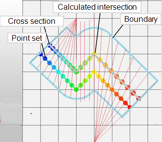
Projection using a non-orthogonal method. This method is chosen to prevent duplication and blind spots around the corners of the cross section panes when displaying wellbore or point set data. click to enlarge
The greater the projection distance, the larger the (possible) distortion of the projected wellbores and point set data, and the higher chance of a mismatch between cross-section backdrop data (e.g. seismic, 3D grid properties) and the projected wellbores and point set data. This effect does not occur when you display wellbores and point set data on a single pane cross section, i.e. a plane section.
Tips for visualizing wellbores and point set data on cross sections
- For single wellbore display, use a wellbore section which follows the wellbore like a curtain. This mitigates the risk of distortion due to projection. To create a wellbore section, you can use the wellbore's context menu Create > Create Wellbore Section or use the Wellbore Section form on the plan strip, see Creating a wellbore section.
-
For multi wellbore or point set cloud display, keep the cross-section pane as close as possible to the wellbore trajectory or point set cloud, and apply a shorter projection distance. You can create the cross section pane graphically using the cross section tool (
 ) in the 3D View. For wellbores you can also create such a connected wellbore section using the cross-section form
 - Use a combination of the 3D View and Cross Section/Seicmic View to be aware of possible projection artifacts.
Adding wells to groups
While some groups are automatically populated with wells, as is the case with groups created by cross section or in the Group View, you can also manually add wells to a group. There are two methods that can be used to add wells to a group:
- In the JewelExplorer, drag and drop a well, or selection of wells, into the target group. To add multiple wells to a group in one action, hold the Ctrl or Shift key on your keyboard and click each of the wells you want to add. When finished creating your selection, click and drag one of the selected wells to the target group; this will add your entire selection to the group.
- In the JewelExplorer, right-click on the well(s) of interest to open the context menu, hover over the Add to group option and select the target group from the list. To add multiple wells to a group in one action, hold the Ctrl or Shift key on your keyboard and click each of the wells you want to move. When finished creating your selection, right-click one of the wells to open the context menu, hover over the Add to group option and select the target group from the list; this will add your entire selection to the group.
To aid in evaluating well data in the Well View, the same well can have multiple instances inside a single group. This, combined with the ability to reorder the wells in your group (see below), allows you to more easily visualize a well of interest next to supporting or related data.
Ordering wells in a group
Especially with groups that were automatically populated from a cross section or Group view filter, you may find it necessary to re-order the wells in the group. This is an important consideration if you intend to visualize the group in the Well View and want to view the wells in a certain order.
- To manually order the wells, find the group of interest in the JewelExplorer and expand the group so that all of the wells are visible. Click and drag the wells into the desired order.